Rack railway
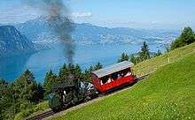
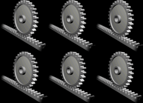
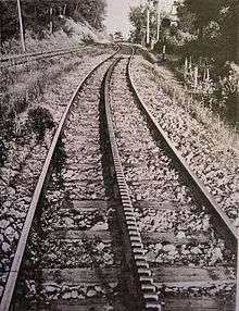
A rack railway (also rack-and-pinion railway, cog railway) is a steep grade railway with a toothed rack rail, usually between the running rails. The trains are fitted with one or more cog wheels or pinions that mesh with this rack rail. This allows the trains to operate on steep grades above around 7 to 10%, which is the maximum for friction-based rail. Most rack railways are mountain railways, although a few are transit railways or tramways built to overcome a steep gradient in an urban environment.
The first cog railway was the Middleton Railway between Middleton and Leeds in West Yorkshire, England, UK, where the first commercially successful steam locomotive, Salamanca, ran in 1812. This used a rack and pinion system designed and patented in 1811 by John Blenkinsop.[1]
The first mountain cog railway was the Mount Washington Cog Railway in the US state of New Hampshire, which carried its first fare-paying passengers in 1868. The track was completed to reach the summit of Mount Washington in 1869. The first mountain rack railway in continental Europe was the Vitznau-Rigi-Bahn on Mount Rigi in Switzerland, which opened in 1871. Both lines are still running.
Rack systems

A number of different rack systems have been developed. Today, the majority of rack railways use the Abt system.
Blenkinsop
.jpg)
John Blenkinsop thought that the friction would be too low of metal wheels on metal rails, so he built his locomotives for the Middleton Railway in 1812 with a 20 tooth, 3 feet (914 mm) diameter cog wheel (pinion) on the left side that engaged in rack teeth (two teeth per foot) on the outer side of the rail, the metal "fishbelly" edge rail with its side rack being cast all in one piece, in three feet (one yard) lengths. Blenkinsop's system remained in use for 25 years on the Middleton Railway, but it became a curiosity because simple friction was found to be sufficient for railroads operating on level ground.[2]
Rack systems place the rack rail halfway between the running rails, with the exception of some early Morgan rack installations.
Marsh
The first successful rack railway in the US was the Mount Washington Cog Railway, developed by Sylvester Marsh.[3] Marsh was issued a U.S. patent for the general idea of a rack railway in September 1861,[4] and in January 1867 for a practical rack where the gear teeth take the form of rollers arranged like the rungs of a ladder between two L-shaped wrought-iron rails.[5] The first public trial of the Marsh rack on Mount Washington was made on August 29, 1866, when only one quarter of a mile (402 meters) of track had been completed. The Mount Washington railway opened to the public on August 14, 1868.[6] The pinion wheels on the locomotives have deep teeth that ensure that at least two teeth are engaged with the rack at all times; this measure helps reduce the possibility of the pinions riding up and out of the rack.[1]
Riggenbach
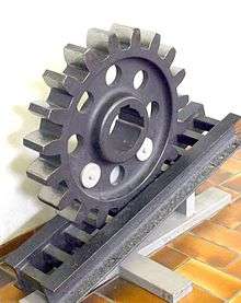
The Riggenbach rack system was invented by Niklaus Riggenbach working at about the same time as, but independently from Marsh. Riggenbach was granted a French patent in 1863 based on a working model which he used to interest potential Swiss backers. During this time, the Swiss Consul to the United States visited Marsh's Mount Washington Cog Railway and reported back with enthusiasm to the Swiss government. Eager to boost tourism in Switzerland, the government commissioned Riggenbach to build a rack railway up Rigi Mountain. Following the construction of a prototype locomotive and test track in a quarry near Bern, the Vitznau-Rigi-Bahn opened on 22 May 1871.[1]
The Riggenbach system is similar in design to the Marsh system. It uses a ladder rack, formed of steel plates or channels connected by round or square rods at regular intervals. The Riggenbach system suffers from the problem that its fixed ladder rack is more complex and expensive to build than the other systems.
Following the success of the Vitznau-Rigi-Bahn, Riggenbach established the Maschinenfabrik der Internationalen Gesellschaft für Bergbahnen (IGB) - a company that produced rack locomotives to his design.[1]
Strub
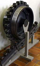
The Strub rack system was invented by Emil Strub in 1896. It uses a rolled flat-bottom rail with rack teeth machined into the head approximately 100 mm apart. Safety jaws fitted to the locomotive engage with the underside of the head to prevent derailments and serve as a brake.[1] Strub's US Patent, granted in 1898, also includes details of how the rack rail is integrated with the mechanism of a turnout.[7]
The best-known use of the Strub system is on the Jungfraubahn in Switzerland.[1] It is the simplest rack system to maintain and has become increasingly popular.
Morgan
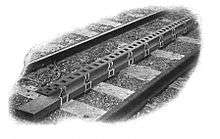
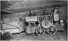
In 1900, E. C. Morgan of Chicago received a patent on a rack railway system that was mechanically similar to the Riggenbach rack, but where the rack was also used as a third rail to power the electric locomotive.[8] Morgan went on to develop heavier locomotives[9] and with J. H. Morgan, turnouts for this system.[10] In 1904, he patented a simplified but compatible rack, where the teeth on the engine pinions engaged square holes punched in a bar-shaped center rail.[11] J. H. Morgan patented several alternative turnout designs for use with this rack system.[12][13] Curiously, Morgan recommended an off-center rack in order to allow clear passage for pedestrians and animals walking along the tracks.[8] Some photos of early Morgan installations show this.[14] A simplified rack mounting system could be used when the Morgan rack was not used for third-rail power[15] and the Morgan rack offered interesting possibilities for street railways.[16] The Morgan rack was good for grades of up to 16 percent.[17]
The Goodman Equipment Company began marketing the Morgan system to mining companies, and it saw widespread use, particularly where steep grades were encountered underground.[18][19][20] By 1907, Goodman had offices in Cardiff, Wales to serve the British market.[14] Between 1903 and 1909, the McKell Coal and Coke company in Raleigh County, West Virginia, installed 35,000 feet (10,700 m) of Morgan rack/third-rail track in its mines.[21] Between 1905 and 1906, the Mammoth Vein Coal Company installed 8,200 feet (2,500 m) of powered rack in two of its mines in Everist, Iowa, with a maximum grade of 16%.[22] The Donohoe Coke Co. of Greenwald, Pennsylvania had 10,000 feet (3,050 m) of Goodman rack in its mine in 1906.[23] The Morgan system saw limited use on one common carrier railroad in the United States, the Chicago Tunnel Company, a narrow gauge freight carrier that had one steep grade in the line up to their surface disposal station on the Chicago lakefront.[24]
Abt
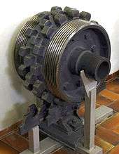
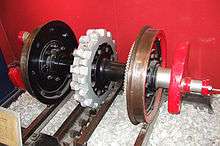
The Abt system was devised by Roman Abt, a Swiss locomotive engineer. Abt worked for Riggenbach at his works in Olten and later at his IGB rack locomotive company. In 1885, he founded his own civil engineering company.[1]
During the early 1880s, Abt worked to devise an improved rack system that overcame the limitations of the Riggenbach system. In particular, the Riggenbach rack was expensive to manufacture and maintain and the switches were complex. In 1882, Abt designed a new rack using solid bars with vertical teeth machined into them. Two or three of these bars are mounted centrally between the rails, with the teeth offset.[25] The use of multiple bars with offset teeth ensures that the pinions on the locomotive driving wheels are constantly engaged with the rack.[26] The Abt system is cheaper to build than the Riggenbach because it requires a lower weight of rack over a given length. However the Riggenbach system exhibits greater wear resistance than the Abt.[1]
Abt also developed a system for smoothing the transition from friction to rack traction, using a spring-mounted rack section to bring the pinion teeth gradually into engagement.[27]
The first use of the Abt system was on the Harzbahn in Germany which opened in 1885.[1]
The pinion wheels can be mounted on the same axle as the rail wheels (as in the picture at left), or driven separately. The steam locomotives on the Mount Lyell Mining and Railway Company had separate cylinders driving the pinion wheel, as do the 'X' Class locomotives on the Nilgiri Mountain Railway.
- The steepest gradient on the rack section of Mount Lyell Mining and Railway Company was 1 in 15 (6.67%),[28]
- The steepest gradient on the rack section of the Mount Morgan Railway was 1 in 16.5 (6,06%).[29]
Locher
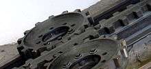
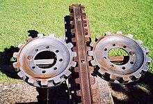
The Locher rack system, invented by Eduard Locher, has gear teeth cut in the sides rather than the top of the rail, engaged by two cog wheels on the locomotive. This system allows use on steeper grades than the other systems, whose teeth could jump out of the rack. It is used on the Pilatus Railway.
Locher set out to design a rack system that could be used on gradients as steep as 1 in 2 (50%). The Abt system - the most common rack system in Switzerland at the time - was limited to a maximum gradient of 1 in 4 (25%). Locher showed that on steeper grade, the Abt system was prone to the driving pinion over-riding the rack, causing potentially catastrophic derailments, as predicted by Dr. Abt. To overcome this problem and allow a rack line up the steep sides of Mt. Pilatus, Locher developed a rack system where the rack is a flat bar with symmetrical, horizontal teeth. Horizontal pinions engage the centrally-mounted bar, both driving the locomotive and keeping it centered on the track.
This system provides very stable attachment to the track, also protecting the car from toppling over even under the most severe crosswinds. Such gears are also capable of leading the car, so even flanges on running wheels are optional. The biggest shortcoming of the system is that the standard railway switch is not usable, and a transfer table or other complex device must be used where branching of the track is needed.
Following tests, the Locher system was deployed on the Pilatus Railway, which opened in 1889. No other public railway uses the Locher system, although some European coal mines use a similar system on steeply graded underground lines.[1]
Lamella

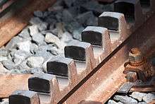
The Lamella system (also known as the Von Roll system) was developed by the Von Roll company after the rolled steel rails used in the Strub system became unavailable. It is formed from a single blade cut in a similar fashion to the Abt system but typically wider than a single Abt bar. The Lamella rack can be used by locomotives designed for use on the Riggenbach or the Strub systems, so long as the safety-jaws that were a feature of the original Strub system are not used. Some railways use rack from multiple systems; for example, the St. Gallen Gais Appenzell Railway in Switzerland has sections of Riggenbach, Strub and Lamella rack.[1]
Most of the rack railways built from the late 20th century onwards have used the Lamella system.[1]
Rack-and-adhesion systems / Pure rack systems
Rack-and-adhesion systems use the cog drive only on the steepest sections and elsewhere operate as a regular railway. Others, the steeper ones, are rack-only. On the latter type, the locomotives' wheels are generally free-wheeling and despite appearances do not contribute to driving the train. In this case the racks continue also in the horizontal parts, if any.
Fell
The Fell mountain railway system is not strictly speaking a rack railway since there are no cogs with teeth. Rather, this system uses a smooth raised centre rail between the two running rails on steep lines which is gripped on both sides to improve friction. Trains are propelled by wheels or braked by shoes pressed horizontally onto the centre rail, as well as by means of the normal running wheels.
Switches
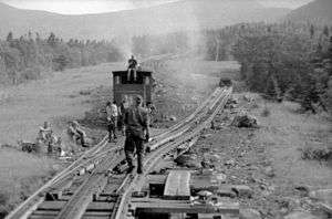
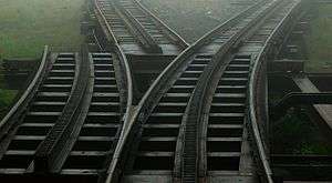
Rack railway switches are as varied as rack railway technologies, for optional rack lines such as the Zentralbahn in Switzerland and the West Coast Wilderness Railway in Tasmania it is convenient to only use switches on sections flat enough for adhesion (for example, on a pass summit). Other systems which rely on the rack for driving (with the conventional rail wheels undriven) such as the Dolderbahn in Zurich, Štrbské Pleso in Slovakia and the Schynige Platte rack railway instead must switch the rack rail. The Dolderbahn switch works by bending all three rails, an operation that is performed every trip as the two trains pass in the middle.
The geometry of the rack system has a large impact on the construction of turnouts. If the rack is elevated above the running rails, there is no need to interrupt the running rails to allow passage of the driving pinions of the engines. Strub explicitly documented this in his U.S. patent.[7] Strub used a complex set of bell-cranks and push-rods linking the throw-rod for the points to the two throw-rods for the moving rack sections. One break in the rack was required to select between the two routes, and a second break was required where the rack rails cross the running rails. Turnouts for the Morgan Rack system were similar, with the rack elevated above the running rails. Most of the Morgan turnout patents included movable rack sections to avoid breaks in the rack,[10][13] but because all Morgan locomotives had two linked drive pinions, there was no need for a continuous rack. So long as the breaks in the rack were shorter than the distance between the drive pinions on the locomotive, the rack rail could be interrupted wherever there was need to cross over a running rail.[8]
Turnouts are far more complex when the rack is at or below the level of the running rails. Marsh's first rack patent shows such an arrangement,[4] and the original Mount Washington Cog Railway he built had no turnouts. It was not until 1941 that a turnout was constructed on this line.[30] There were more turnouts built for the line but all were hand operated. In 2003, a new automatic hydraulic turnout was developed and built at the base as a prototype. With the success of the new turnout, more new automatic hydraulic turnouts were built to replace the hand-operated ones. The new turnouts installed on the Mount Washington line in 2007 are essentially transfer tables.[31] The Locher rack also requires transfer tables.
Cog locomotives

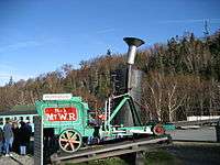
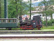
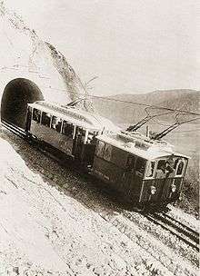
Originally almost all cog railways were powered by steam locomotives. The steam locomotive needs to be extensively modified to work effectively in this environment. Unlike a diesel locomotive or electric locomotive, the steam locomotive only works when its powerplant (the boiler, in this case) is fairly level. The locomotive boiler requires water to cover the boiler tubes and firebox sheets at all times, particularly the crown sheet, the metal top of the firebox. If this is not covered with water, the heat of the fire will soften it enough to give way under the boiler pressure, leading to a catastrophic failure.
On rack systems with extreme gradients, the boiler, cab and general superstructure of the locomotive are tilted forward relative to the wheels so that they are more or less horizontal when on the steeply graded track. These locomotives often cannot function on level track, and so the entire line, including maintenance shops, must be laid on a gradient. This is one of the reasons why rack railways were among the first to be electrified and most of today's rack railways are electrically powered. In some cases, the vertical boiler can be used that is less sensitive for the track gradient.
On a rack-only railroad, locomotives are always downward of their passenger cars for safety reasons: the locomotive is fitted with powerful brakes, often including hooks or clamps that grip the rack rail solidly. Some locomotives are fitted with automatic brakes that apply if the speed gets too high, preventing runaways. Often there is no coupler between locomotive and train since gravity will always push the passenger car down against the locomotive. Electrically powered vehicles often have electromagnetic track brakes as well.
The maximum speed of trains operating on a cog railway is very low, generally from 9 to 25 km/h (6 to 16 mph) depending on gradient and propulsion method. Because the Skitube has gentler gradients than typical, its speeds are higher than typical.
List of cog and rack railways
Angola
- Lengue gorge.[32]
- on Benguela railway - 1906[33]
Argentina
- Transandine Railway between Mendoza and Santa Rosa de Los Andes, Chile, see Chile below.
Australia
- West Coast Wilderness Railway in Tasmania, originally opened in 1896 to service the Mount Lyell copper mine and closed and completely removed in 1960s. Rebuilt and re-opened for tourists in 2003. Uses the Abt rack system. 1,067 mm (3 ft 6 in) gauge.
- Mt Morgan Rack Railway on Mount Morgan - rack system existed until 1952 when the line was deviated. Uses the Abt rack system. 1,067 mm (3 ft 6 in) gauge.
- Ellalong Colliery - underground Lamella rack - installed in 1984
- Skitube Alpine Railway - Lamella rack - in the Snowy Mountains, opened in 1987; 1,435 mm (4 ft 8 1⁄2 in) gauge.
- Blue Mountains sewerage project - temporary 610 mm (2 ft) gauge construction railway, 1995
Austria
- Achensee Railway (Achenseebahn), Tyrol 1,000 mm (3 ft 3 3⁄8 in)
- Erzberg Railway (Erzbergbahn), Styria
- Gaisberg Railway (Gaisbergbahn), Gaisberg (1887–1928)
- Kahlenberg Railway (Kahlenbergbahn), Kahlenberg, Döbling, Vienna (1872–1920)
- Schafberg Railway (Schafbergbahn), Upper Austria 1,000 mm (3 ft 3 3⁄8 in)
- Schneeberg Railway (Schneebergbahn), Lower Austria
Bolivia
Brazil
- Corcovado Rack Railway
- The Estrada de Ferro Santos-Jundiaí which became part of Rede Ferroviária Federal Sociedade Anônima (RFFSA) 1957-1997, now owned by MRS Logística. 1,600 mm (5 ft 3 in) gauge between Paranapiacaba and Raiz de Serra.
- Teresopolis and Petropolis railways, both out of service, near Rio de Janeiro. More on German page!
Chile
- Arica–La Paz railway, Arica–La Paz
- Santa Lucía Hill tramway (Abt system), Santiago (1902–1910)[34]
- The Transandine Railway, Santa Rosa de Los Andes - Mendoza, Argentina The rebuild will be adhesion only and use a base tunnel.[35]
Czech Republic
France
- Lyon Metro Line C
- Mont Blanc Tramway
- Montenvers Railway
- Petit train de la Rhune
- Panoramique des Domes
Germany
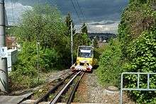
- Drachenfels Railway (Drachenfelsbahn)
- Harz Railway (Harzbahn)
- Rübeland Railway (Rübelandbahn)
- Höllentalbahn (adhesion only since 1933)
- Murg Valley Railway (adhesion only since 1926)
- Oberweißbach Mountain Railway (Oberweißbacher Bergbahn)
- Schwarza Valley Railway (Schwarzatalbahn)
- Stuttgart Rack Railway, Stuttgart
- Wendelstein Railway (Wendelsteinbahn)
- Bavarian Zugspitze Railway (Bayerische Zugspitzbahn)
Greece
Hungary
- Fogaskerekű Vasút in Budapest, Hungary is a kind of cog-wheel tram in the hilly Buda part of the city.
Indonesia

- The former State Railways of West Sumatra's line between Kayutanam and Batutabal (reactivation pending), and Padang Panjang to Payakumbuh (disused).
- The former Netherlands East Indies Railways' line between Ambarawa and Gemawang, on the Kedungjati-Ambarawa-Magelang-Yogyakarta line. Only the Ambarawa-Bedono section is in operation as a tourist line.
India
- Nilgiri Mountain Railway, in the Indian state of Tamil Nadu is also a World Heritage Site. Runs twice a day using steam powered 'X' Class locomotives built by the Swiss Locomotive and Machine Works.
Italy
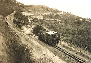
- Mont Cenis Pass Railway ; temporary while main tunnel built.
- Vesuvius Funicular (1880–1944; originally built as a funicular and then changed to a rack railway. It was the only railway climbing an active volcano. It was destroyed various times by Vesuvius eruptions. With its last destruction in 1944, it was never built again. It is famous worldwide as a result of the song Funiculì Funiculà written about it)
- Opicina Tramway (1902–1928; rack replaced with a funicular section)
- Rittnerbahn (rack section closed)
- Superga Rack Railway
- Principe–Granarolo rack railway in the city of Genoa
- S.Ellero - Saltino (1892–1922; it was the first rack railway built in Italy)
- Lagonegro-Castrovillari-Spezzano Albanese of Ferrovie Calabro Lucane (1915–1978; it consisted of a series of separated lines which had to be unified into a single one but the project was never completed)
- Vibo Valentia-Mileto of Ferrovie Calabro Lucane (1917–1966; it was a local rack railway localized in south Italy)
- Rocchette-Asiago (1910–1958; it was the highest Italian rack railway)
- Catanzaro Città - Catanzaro Sala of Ferrovie della Calabria (Actually on service; it connects the city of Catanzaro to the borough of Sala)
- Paola-Cosenza of Ferrovie dello Stato (1915–1987; it was replaced by a tunnel)
- Saline-Volterra of Ferrovie dello Stato (1863–1958; it was part of a railway which connected Cecina to Volterra. Downstream flat line, from Cecina to Saline, is actually on service)
- Dittaino-Leonforte of Ferrovie dello Stato (1918–1959; it was located on the island of Sicily)
- Dittaino-Piazza Armerina of Ferrovie dello Stato (1912–1971; it was dismissed after a series of landslides which damaged some parts of the line)
- Lercara Bassa-Filaga-Palazzo Adriano-Magazzolo of Ferrovie dello Stato (1924–1959; it was used for mining and workers transports in Sicily )
- Agrigento-Naro-Licata (1911–1960; it was used to transport sulfur extracted from mines located on the island of Sicily)
Japan
- Ikawa Line, Oigawa Railway
- Usui Pass was the first rack and pinion line in Japan, on the Shin-Etsu Line of the then Japanese National Railway. It was replaced in 1963 by a new parallel adhesion line, and in turn replaced by the Nagano Shinkansen line opened for the 1998 Winter Olympics at Nagano.
Lebanon
Mexico
- The 762 mm (2 ft 6 in) gauge Mapimi Railroad in Durango State had a short Abt rack section from El Cambio to Ojuela. The maximum grade was 13.6% and it was worked by two Baldwin 0-6-2T steam locomotives built in 1896 and two Baldwin 2-6-2T steam locomotives built in 1898 and 1900. The railroad closed in the early 1930s.[36]
Panama
- Large ships are guided through the Panama Canal Locks by electric locomotives known as mulas (mules), running on rack rails on the lock walls. The new locks, projected to open in 2015, will use tugs.
Portugal
- There was previously a cog railway from Funchal to Monte in Madeira Island, which operated between 1893 and 1943, and went further up to Terreiro da Luta at 867 m above sea level.
Slovakia
- Štrbské Pleso - Štrba rack railway
- Brezno - Tisovec rack railway
South Africa
- There used to be a Riggenbach rack railway built by the NZASM between Waterval Boven and Waterval Onder. It was in operation until 1908.[37] 3 ft 6 in (1,067 mm) gauge.
Spain
Switzerland
- Appenzeller Bahnen
- Bergbahn Rheineck-Walzenhausen (RhW)
- Berner Oberland Bahn, also owning Schynige Platte Railway
- Chemin de fer Aigle-Leysin
- Chemin de fer Aigle-Ollon-Monthey-Champéry
- Chemin de fer Bex-Villars-Bretaye
- Chemin de fer Blonay - Les Pléiades
- Brienz Rothorn Bahn
- Chemin de Fer de Martigny au Châtelard (MC)
- Chemin de fer Montreux-Glion-Rochers-de-Naye
- Dampfbahn Furka-Bergstrecke (DFB)
- Dolderbahn (Db)
- Gornergratbahn (owned by BVZ Holding and managed by MGB)
- Joweid Zahnradbahn (a now closed freight line)
- Jungfraubahn - the highest rack railway in Europe
- Matterhorn-Gotthard Railway (MGB) (former Furka-Oberalp-Bahn and Brig-Visp-Zermatt Railway)
- Monte Generoso Railway
- Pilatus Railway
- Rigi-Bahnen (Arth-Rigi and Vitznau-Rigi railways)
- Rorschach-Heiden-Bahn, Rorschach to Heiden
- Wengernalpbahn - the longest continuous rack railway in the world
- Zentralbahn (Zb) (former Swiss Federal Railway's Brünigbahn and Luzern-Stans-Engelberg-Bahn)
United Kingdom
United States
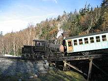
- The Chicago Tunnel Company (abandoned) used the Morgan rack system on the steep grade up to Grant Park.
- Manitou and Pike's Peak Railway, Manitou Springs, Colorado. Swiss-made Diesel-Pneumatic railcars, 1- or 2-car trains. Abt rack system.
- Mount Washington Cog Railway, Bretton Woods, New Hampshire. Bio Diesel & live steam cog train operations with Marsh rack system, world's first to be used as a mountain railway (inaugurated in 1868).
- Quincy and Torch Lake Cog Railway,[38] cog rail tram opened in 1997. Hancock, Michigan.
- Green Mountain Cog Railway (abandoned)
Vietnam
- The Đà Lạt–Tháp Chàm line in Southern Vietnam. Abandoned after the Vietnam War, although a 7 km section remains in use as a tourist attraction.
- Built in the 1920s, the 84 km line had a cogwheel part 34 km long, running through four tunnels with a total length of almost 1,000 meters, taking trains from the Krongpha Pass up the Ngoan Muc (Bellevue) Pass to Da Lat.
Rack railways in fiction
The Culdee Fell Railway is a fictional cog railway on the Island of Sodor in The Railway Series by Rev. W. Awdry. Its operation, locomotives and history are at least in part based on the Snowdon Mountain Railway. It is featured in the book Mountain Engines.
See also
References
- 1 2 3 4 5 6 7 8 9 10 11 12 Jehan, David (2003). Rack Railways of Australia (2nd. ed.). Illawarra Light Railway Museum Society. ISBN 0-9750452-0-2.
- ↑ Roman Abt, Mountain and Rack Railways Cassier's Magazine, Vol. XXXVII, No. 5 (March 1910); page 525.
- ↑ Sylvester Marsh
- 1 2 Sylvester Marsh, Improvement in Locomotive-Engines for Ascending Inclined Planes, U.S. Patent 33,255, September 10, 1861.
- ↑ Sylvester Marsh, Improved Cog-Rail for Railroads, U.S. Patent 61,221, January 15, 1867.
- ↑ C. H. Hitchcock, Chapter IV: The Approaches to Mount Washington, Mount Washington in Winter, Chick and Andrews, Boston, 1871; page 82-85.
- 1 2 Emil Strub, Rack-Rail for Mountain-Railways, U.S. Patent 600,324, March 8, 1898.
- 1 2 3 Edmund C. Morgan, Electric-Railway System U. S. Patent 659,178, October 2, 1900.
- ↑ Edmund C. Morgan, Electric-Railway System U. S. Patent 772,780, October 18, 1904.
- 1 2 Edmund C. Morgan and John H. Morgan, Switching System for Combined Third and Traction Rails for Electric Railways, U. S. Patent 772,732, October 18, 1904.
- ↑ Edmund C. Morgan, Combined Third and Traction Rail for Electric Railways, U. S. Patent 753,803, March 1, 1904.
- ↑ John H. Morgan, Switching or Crossover Device for Traction Rack Rail Systems, U.S. Patent 772,736, October 18, 1904.
- 1 2 John H. Morgan, Throw Rail for Combined Third and Traction Rail Switching, U.S. Patent 772,735, October 18, 1904.
- 1 2 Electric Locomotives, The Electrical Magazine, Vol. VII, No. 3 (March 30, 1907); page 179.
- ↑ Edmund C. Morgan, Cog wheel railway, U.S. Patent 1,203,034, October 31, 1916.
- ↑ Edmund C. Morgan, Traction Rack for Railways, U. S. Patent 772,731, October 18, 1904.
- ↑ Conveying Machinery -- Motor Haulage, Mechanical Engineer's Handbook, McGraw Hill, 1916; page 1145.
- ↑ J. J. Rutledge, Recent Improvements in Coal Mining in Illinois, Mining Magazine Vol. XIII, No. 3 (March 1906); page 186.
- ↑ Frank C. Perkins, Development of Electric Mine Locomotive, The Mining World, Vol XXIX, No. 1 (July 4, 1908); page 3.
- ↑ Goodman Rack Rail Haulage, Goodman Mining Handbook, Goodman Mfg. Co., 1919.
- ↑ H. H. Stock, New River Coal Field, W. VA., Mines and Minerals, Vol. XXIX, No. 11 (June 1909); page 513.
- ↑ E. C. DeWolfe, Operations of Mammoth Vein Coal Co., Bussey, Iowa., The Black Diamond, Vol. 37, No. 5 (August 4, 1906), page 28. Note, the article systematically misspells Everist as Everts, a spelling contradicted by all other sources.
- ↑ Plant of the Donohoe Coke Co., Greenwald, Pa., The Black Diamond, Vol. 37, No. 1 (July 7, 1906), page 28.
- ↑ Third- or Rack-Rail Haulage, Mining and Minerals, May 1904; page 513.
- ↑ Roman Abt, Permanent Way for Mountain Railways, U.S. Patent 284,790, September 11, 1883
- ↑ Roman Abt, Locomotive, U.S. Patent 339,831, April 13, 1886.
- ↑ Roman Abt, Rack-Rail for Railways, U.S. Patent 349,624, September 21, 1886.
- ↑ http://www.queenstowntasmania.com/Railway_Past_And_Future_Page.php
- ↑ http://www.mountmorgan.org.au/history/the-mount-morgan-railway
- ↑ Mount Washington Railway Company Historical Timeline
- ↑ "New Switching System Installed". Cog Railway Media Resources. Mount Washington Cog Railway. Retrieved 14 July 2014.
- ↑ http://trains-worldexpresses.com/700/705.htm
- ↑ http://www.railpage.com.au/f-t11357768-s75.htm
- ↑ Morrison, Allen (1992). The Tramways of Chile: 1858–1978. New York: Bonde Press. pp. 64–65. ISBN 0-9622348-2-6.
- ↑ Se construye
- ↑
- ↑
- ↑ Quincy and Torch Lake Cog Railway
External links
| Wikimedia Commons has media related to Rack rail transport. |
- Liste der Zahnradbahnen (German)
- RAIL-INFO SWITZERLAND
- Mount Washington Railway Company
- Manitou and Pike's Peak Railway
- Winchester, Clarence, ed. (1936), "Rack rail locomotives", Railway Wonders of the World, pp. 804–808 illustrated description of the various types of rack rail systems, including the Wetli
