Plate heat exchanger

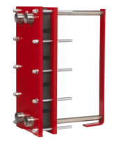
A plate heat exchanger is a type of heat exchanger that uses metal plates to transfer heat between two fluids. This has a major advantage over a conventional heat exchanger in that the fluids are exposed to a much larger surface area because the fluids spread out over the plates. This facilitates the transfer of heat, and greatly increases the speed of the temperature change. Plate heat exchangers are now common and very small brazed versions are used in the hot-water sections of millions of combination boilers. The high heat transfer efficiency for such a small physical size has increased the domestic hot water (DHW) flowrate of combination boilers. The small plate heat exchanger has made a great impact in domestic heating and hot-water. Larger commercial versions use gaskets between the plates, whereas smaller versions tend to be brazed.
The concept behind a heat exchanger is the use of pipes or other containment vessels to heat or cool one fluid by transferring heat between it and another fluid. In most cases, the exchanger consists of a coiled pipe containing one fluid that passes through a chamber containing another fluid. The walls of the pipe are usually made of metal, or another substance with a high thermal conductivity, to facilitate the interchange, whereas the outer casing of the larger chamber is made of a plastic or coated with thermal insulation, to discourage heat from escaping from the exchanger.
The plate heat exchanger (PHE) was invented by Dr Richard Seligman in 1923 and revolutionised methods of indirect heating and cooling of fluids.[1] Dr Richard Seligman founded APV in 1910 as the Aluminium Plant & Vessel Company Limited, a specialist fabricating firm supplying welded vessels to the brewery and vegetable oil trades.
Design of plate and frame heat exchangers


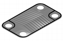
The plate heat exchanger (PHE) is a specialized design well suited to transferring heat between medium- and low-pressure fluids. Welded, semi-welded and brazed heat exchangers are used for heat exchange between high-pressure fluids or where a more compact product is required. In place of a pipe passing through a chamber, there are instead two alternating chambers, usually thin in depth, separated at their largest surface by a corrugated metal plate. The plates used in a plate and frame heat exchanger are obtained by one piece pressing of metal plates. Stainless steel is a commonly used metal for the plates because of its ability to withstand high temperatures, its strength, and its corrosion resistance.
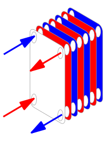
The plates are often spaced by rubber sealing gaskets which are cemented into a section around the edge of the plates. The plates are pressed to form troughs at right angles to the direction of flow of the liquid which runs through the channels in the heat exchanger. These troughs are arranged so that they interlink with the other plates which forms the channel with gaps of 1.3–1.5 mm between the plates. The plates are compressed together in a rigid frame to form an arrangement of parallel flow channels with alternating hot and cold fluids. The plates produce an extremely large surface area, which allows for the fastest possible transfer. Making each chamber thin ensures that the majority of the volume of the liquid contacts the plate, again aiding exchange. The troughs also create and maintain a turbulent flow in the liquid to maximize heat transfer in the exchanger. A high degree of turbulence can be obtained at low flow rates and high heat transfer coefficient can then be achieved.
As compared to shell and tube heat exchangers, the temperature approach in a plate heat exchangers may be as low as 1 °C whereas shell and tube heat exchangers require an approach of 5 °C or more. For the same amount of heat exchanged, the size of the plate heat exchanger is smaller, because of the large heat transfer area afforded by the plates (the large area through which heat can travel). Increase and reduction of the heat transfer area is simple in a plate heat-exchanger, through the addition or removal of plates from the stack.
Evaluating plate heat exchangers
All plate heat exchangers look similar on the outside. The difference lies on the inside, in the details of the plate design and the sealing technologies used. Hence, when evaluating a plate heat exchanger, it is very important not only to explore the details of the product being supplied, but also to analyze the level of research and development carried out by the manufacturer and the post-commissioning service and spare parts availability.
An important aspect to take into account when evaluating a heat exchanger are the forms of corrugation within the heat exchanger. There are two types: intermating and chevron corrugations. In general, greater heat transfer enhancement is produced from chevrons for a given increase in pressure drop and are more commonly used than intermating corrugations.[2]
Optimization of Plate Heat Exchangers
To achieve improvement in PHE's, two important factors namely amount of heat transfer and pressure drop have to be considered such that amount of heat transfer needs to be increased and pressure drops need to be decreased. In plate heat exchangers due to presence of corrugated plate, there is a significant resistance to flow with high friction loss. Thus to design plate heat exchangers, one should consider both factors. For various range of Reynolds numbers, many correlations and chevron angles for plate heat exchangers exist. The plate geometry is one of the most important factor in heat transfer and pressure drop in plate heat exchangers, however such a feature is not accurately prescribed. In the corrugated plate heat exchangers, because of narrow path between the plates, there is a large pressure capacity and the flow becomes turbulent along the path. Therefore, it requires more pumping power than the other types of heat exchangers. Therefore, higher heat transfer and less pressure drop are targeted. The shape of plate heat exchanger is very important for industrial applications that is affecting on the pressure drop.[3]
Flow distribution and heat transfer equation
Design calculations of a plate heat exchanger include flow distribution and pressure drop and heat transfer. The former is an issue of Flow distribution in manifolds.[4] A layout configuration of plate heat exchanger can be usually simplified into a manifold system with two manifold headers for dividing and combining fluids, which can be categorized into U-type and Z-type arrangement according to flow direction in the headers, as shown in manifold arrangement. Bassiouny and Martin developed the previous theory of design.[5][6] In recent years Wang [7][8] unified all the main existing models and developed a most completed theory and design tool.
The total rate of heat transfer between the hot and cold fluids passing through a plate heat exchanger may be expressed as: Q = UA∆Tm where U is the Overall heat transfer coefficient, A is the total plate area, and ∆Tm is the Log mean temperature difference. U is dependent upon the heat transfer coefficients in the hot and cold streams.[2]

See also
| Wikimedia Commons has media related to Plate and frame heat exchangers. |
References
- ↑ "Plate Heat exchangers". Gold-Bar Engineering ltd. Retrieved 30 June 2015.
- 1 2 Hewitt, G (1994). Process Heat Transfer. CRC Press.
- ↑ Sanei, Hamed (2016). "Numerical Investigation On The Effect Of Geometrical Shape Of Plate Heat Exchangers On Heat Transfer Efficiency". international jurnal of Mechanical, Aerospace, Industrial, Mechatoronic and manufacturing Engineering. 10: 798–802.
- ↑ Wang, J.Y. (2011). "Theory of flow distribution in manifolds". Chemical Engineering J. 168 (3): 1331–1345. doi:10.1016/j.cej.2011.02.050.
- ↑ Bassiouny, M.K.; Martin, H. (1984). "Flow distribution and pressure drop in plate heat exchanges. Part I. U-Type arrangement.". Chem. Eng. Sci. 39 (4): 693–700. doi:10.1016/0009-2509(84)80176-1.
- ↑ Bassiouny, M.K.; Martin, H. (1984). "Flow distribution and pressure drop in plate heat exchanges. Part II. Z-Type arrangement.". Chem. Eng. Sci. 39 (4): 701–704. doi:10.1016/0009-2509(84)80177-3.
- ↑ Wang, J.Y. (2008). "Pressure drop and flow distribution in parallel-channel of configurations of fuel cell stacks: U-type arrangement". Int. J. of Hydrogen Energy. 33 (21): 6339–6350. doi:10.1016/j.ijhydene.2008.08.020.
- ↑ Wang, J.Y. (2010). "Pressure drop and flow distribution in parallel-channel of configurations of fuel cell stacks: Z-type arrangement". Int. J. of Hydrogen Energy. 35 (11): 5498–5509. doi:10.1016/j.ijhydene.2010.02.131.
Bibliography
- Sadik Kakac and Hongtan Liu (March 2002). Heat Exchangers: Selection, Rating and Thermal Design (2nd ed.). CRC Press. ISBN 0-8493-0902-6.
- T. Kuppan (February 2000). Heat Exchanger Design Handbook (1st ed.). CRC Press. ISBN 0-8247-9787-6.
- J. M. Coulson and J. F. Richardson (1999). Coulson & Richarson's Chemical Engineering Volume 1 (6th ed.). Butterworth Heinemann. ISBN 0-7506-4444-3.
External links
- Optimization Of Plate Heat Exchangers by Hamed Sanei, Mohammad Bagher Ayani.
- Plate Heat Exchanger Selection and Sizing
- Heat Exchangers at DMOZ
- Plate heat exchanger
- plate heat exchangers what they are and how they work
- Plate heat exchanger applications
- A list of published articles pertaining to plate heat exchangers
- A screening method for the optimal selection of plate heat exchanger configurations by J.M.Pinto and J.A.W.Gut, University of São Paulo, Brazil.
- Seeking the optimal design of a typical plate heat exchanger (PHE) by Athanasios G. Kanaris, Aikaterini A. Mouza and Spiros V. Paras, Aristotle University of Thessaloniki.