Point spread function
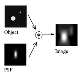
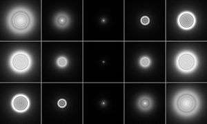
The point spread function (PSF) describes the response of an imaging system to a point source or point object. A more general term for the PSF is a system's impulse response, the PSF being the impulse response of a focused optical system. The PSF in many contexts can be thought of as the extended blob in an image that represents an unresolved object. In functional terms it is the spatial domain version of the transfer function of the imaging system. It is a useful concept in Fourier optics, astronomical imaging, medical imaging, electron microscopy and other imaging techniques such as 3D microscopy (like in confocal laser scanning microscopy) and fluorescence microscopy. The degree of spreading (blurring) of the point object is a measure for the quality of an imaging system. In non-coherent imaging systems such as fluorescent microscopes, telescopes or optical microscopes, the image formation process is linear in power and described by linear system theory. This means that when two objects A and B are imaged simultaneously, the result is equal to the sum of the independently imaged objects. In other words: the imaging of A is unaffected by the imaging of B and vice versa, owing to the non-interacting property of photons. The image of a complex object can then be seen as a convolution of the true object and the PSF. However, when the detected light is coherent, image formation is linear in the complex field. Recording the intensity image then can lead to cancellations or other non-linear effects.
Introduction
By virtue of the linearity property of optical imaging systems, i.e.,
- Image(Object1 + Object2) = Image(Object1) + Image(Object2)
the image of an object in a microscope or telescope can be computed by expressing the object-plane field as a weighted sum over 2D impulse functions, and then expressing the image plane field as the weighted sum over the images of these impulse functions. This is known as the superposition principle, valid for linear systems. The images of the individual object-plane impulse functions are called point spread functions, reflecting the fact that a mathematical point of light in the object plane is spread out to form a finite area in the image plane (in some branches of mathematics and physics, these might be referred to as Green's functions or impulse response functions).
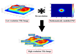
When the object is divided into discrete point objects of varying intensity, the image is computed as a sum of the PSF of each point. As the PSF is typically determined entirely by the imaging system (that is, microscope or telescope), the entire image can be described by knowing the optical properties of the system. This process is usually formulated by a convolution equation. In microscope image processing and astronomy, knowing the PSF of the measuring device is very important for restoring the (original) image with deconvolution. For the case of laser beams, the PSF can be mathematically modeled using the concepts of Gaussian beams.[2] For instance, as shown in the figure on the right, deconvolution of the mathematically modeled PSF and the image, improves the resolution from 2.2 mm to 0.2 mm.[1]
Theory
The point spread function may be independent of position in the object plane, in which case it is called shift invariant. In addition, if there is no distortion in the system, the image plane coordinates are linearly related to the object plane coordinates via the magnification M as:
- .
If the imaging system produces an inverted image, we may simply regard the image plane coordinate axes as being reversed from the object plane axes. With these two assumptions, i.e., that the PSF is shift-invariant and that there is no distortion, calculating the image plane convolution integral is a straightforward process.
Mathematically, we may represent the object plane field as:
i.e., as a sum over weighted impulse functions, although this is also really just stating the sifting property of 2D delta functions (discussed further below). Rewriting the object transmittance function in the form above allows us to calculate the image plane field as the superposition of the images of each of the individual impulse functions, i.e., as a superposition over weighted point spread functions in the image plane using the same weighting function as in the object plane, i.e., . Mathematically, the image is expressed as:
in which PSF(xi /M − u, yi /M − v) is the image of the impulse function δ(xo − u, yo − v).
The 2D impulse function may be regarded as the limit (as side dimension w tends to zero) of the "square post" function, shown in the figure below.

We imagine the object plane as being decomposed into square areas such as this, with each having its own associated square post function. If the height, h, of the post is maintained at 1/w2, then as the side dimension w tends to zero, the height, h, tends to infinity in such a way that the volume (integral) remains constant at 1. This gives the 2D impulse the sifting property (which is implied in the equation above), which says that when the 2D impulse function, δ(x − u,y − v), is integrated against any other continuous function, f(u,v), it "sifts out" the value of f at the location of the impulse, i.e., at the point (x,y).
Since the concept of a perfect point source object is so central to the idea of PSF, it's worth spending some time on that before proceeding further. First of all, there is no such thing in nature as a perfect mathematical point source radiator; the concept is completely non-physical and is nothing more than a mathematical construct used to model and understand optical imaging systems. The utility of the point source concept comes from the fact that a point source in the 2D object plane can only radiate a perfect uniform-amplitude, spherical wave — a wave having perfectly spherical, outward travelling phase fronts with uniform intensity everywhere on the spheres (see Huygens–Fresnel principle). Such a source of uniform spherical waves is shown in the figure below. We also note that a perfect point source radiator will not only radiate a uniform spectrum of propagating plane waves, but a uniform spectrum of exponentially decaying (evanescent) waves as well, and it is these which are responsible for resolution finer than one wavelength (see Fourier optics). This follows from the following Fourier transform expression for a 2D impulse function,

The quadratic lens intercepts a portion of this spherical wave, and refocuses it onto a blurred point in the image plane. For a single lens, an on-axis point source in the object plane produces an Airy disc PSF in the image plane. This comes about in the following way. It can be shown (see Fourier optics, Huygens–Fresnel principle, Fraunhofer diffraction) that the field radiated by a planar object (or, by reciprocity, the field converging onto a planar image) is related to its corresponding source (or image) plane distribution via a Fourier transform (FT) relation. In addition, a uniform function over a circular area (in one FT domain) corresponds to the Airy function, J1(x)/x in the other FT domain, where J1(x) is the first-order Bessel function of the first kind. That is, a uniformly-illuminated circular aperture that passes a converging uniform spherical wave yields an Airy function image at the focal plane. A graph of a sample 2D Airy function is shown in the adjoining figure.

Therefore, the converging (partial) spherical wave shown in the figure above produces an Airy disc in the image plane. The argument of the Airy function is important, because this determines the scaling of the Airy disc (in other words, how big the disc is in the image plane). If Θmax is the maximum angle that the converging waves make with the lens axis, r is radial distance in the image plane, and wavenumber k = 2π/λ where λ = wavelength, then the argument of the Airy function is: kr tan(Θmax). If Θmax is small (only a small portion of the converging spherical wave is available to form the image), then radial distance, r, has to be very large before the total argument of the Airy function moves away from the central spot. In other words, if Θmax is small, the Airy disc is large (which is just another statement of Heisenberg's uncertainty principle for FT pairs, namely that small extent in one domain corresponds to wide extent in the other domain, and the two are related via the space-bandwidth product). By virtue of this, high magnification systems, which typically have small values of Θmax (by the Abbe sine condition), can have more blur in the image, owing to the broader PSF. The size of the PSF is proportional to the magnification, so that the blur is no worse in a relative sense, but it is definitely worse in an absolute sense.
In the figure above, illustrating the truncation of the incident spherical wave by the lens, we may note one very significant fact. In order to measure the point spread function — or impulse response function — of the lens, we do not need a perfect point source that radiates a perfect spherical wave in all directions of space. This is because our lens has only a finite (angular) bandwidth, or finite intercept angle. Therefore, any angular bandwidth contained in the source, which extends past the edge angle of the lens (i.e., lies outside the bandwidth of the system), is essentially wasted source bandwidth because the lens can't intercept it in order to process it. As a result, a perfect point source is not required in order to measure a perfect point spread function. All we need is a light source which has at least as much angular bandwidth as the lens being tested (and of course, is uniform over that angular sector). In other words, we only require a point source which is produced by a convergent (uniform) spherical wave whose half angle is greater than the edge angle of the lens.
History and methods
The diffraction theory of point-spread functions was first studied by Airy in the nineteenth century. He developed an expression for the point-spread function amplitude and intensity of a perfect instrument, free of aberrations (the so-called Airy disc). The theory of aberrated point-spread functions close to the optimum focal plane was studied by the Dutch physicists Frits Zernike and Nijboer in the 1930–40s. A central role in their analysis is played by Zernike's circle polynomials that allow an efficient representation of the aberrations of any optical system with rotational symmetry. Recent analytic results have made it possible to extend Nijboer and Zernike's approach for point-spread function evaluation to a large volume around the optimum focal point. This extended Nijboer-Zernike (ENZ) theory is instrumental in studying the imperfect imaging of three-dimensional objects in confocal microscopy or astronomy under non-ideal imaging conditions. The ENZ-theory has also been applied to the characterization of optical instruments with respect to their aberration by measuring the through-focus intensity distribution and solving an appropriate inverse problem.
PSF in microscopy
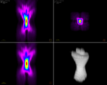
In microscopy, experimental determination of PSF requires sub-resolution (point-like) radiating sources. quantum dots and fluorescent beads are usually considered for this purpose.[3][4] Theoretical models as described above, on the other hand, allow the detailed calculation of the PSF for various imaging conditions. The most compact diffraction limited shape of the PSF is usually preferred. However, by using appropriate optical elements (e.g., a spatial light modulator) the shape of the PSF can be engineered towards different applications.
The PSF in astronomy
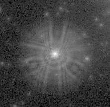
In observational astronomy the experimental determination of a PSF is often very straightforward due to the ample supply of point sources (stars or quasars). The form and source of the PSF may vary widely depending on the instrument and the context in which it is used.
For radio telescopes and diffraction-limited space telescopes the dominant terms in the PSF may be inferred from the configuration of the aperture in the Fourier domain. In practice there may be multiple terms contributed by the various components in a complex optical system. A complete description of the PSF will also include diffusion of light (or photo-electrons) in the detector, as well as tracking errors in the spacecraft or telescope.
For ground based optical telescopes, atmospheric turbulence (known as astronomical seeing) dominates the contribution to the PSF. In high-resolution ground-based imaging, the PSF is often found to vary with position in the image (an effect called anisoplanatism). In ground based adaptive optics systems the PSF is a combination of the aperture of the system with residual uncorrected atmospheric terms.
Point spread functions in ophthalmology
PSFs have recently become a useful diagnostic tool in clinical ophthalmology. Patients are measured with a wavefront sensor, and special software calculates the PSF for that patient's eye. In this manner a physician can "see" what the patient sees. This method also allows a physician to simulate potential treatments on a patient, and see how those treatments would alter the patient's PSF. Additionally, once measured the PSF can be minimized using an adaptive optics system. This, in conjunction with a CCD, can be used to visualize anatomical structures not otherwise visible in vivo, such as cone photoreceptors.
See also
- Circle of confusion, for the closely related topic in general photography.
- Airy disc
- Encircled energy
- PSF Lab
- Deconvolution
- Microscope
- Microsphere
References
- 1 2 Ahi, Kiarash; Anwar, Mehdi (May 26, 2016). "Developing terahertz imaging equation and enhancement of the resolution of terahertz images using deconvolution". Proc. SPIE 9856, Terahertz Physics, Devices, and Systems X: Advanced Applications in Industry and Defense, 98560N. doi:10.1117/12.2228680.
- ↑ Ahi, Kiarash; Anwar, Mehdi (May 26, 2016). "Modeling of terahertz images based on x-ray images: a novel approach for verification of terahertz images and identification of objects with fine details beyond terahertz resolution". Proc. SPIE 9856, Terahertz Physics, Devices, and Systems X: Advanced Applications in Industry and Defense, 98560N. doi:10.1117/12.2228685.
- ↑ Light transmitted through minute holes in a thin layer of silver vacuum or chemically deposited on a slide or cover-slip have also been used, as they are bright and do not photo-bleach. S. Courty; C. Bouzigues; C. Luccardini; M-V Ehrensperger; S. Bonneau & M. Dahan (2006). "Tracking individual proteins in living cells using single quantum dot imaging". In James Inglese. Methods in enzymology: Measuring biological responses with automated microscopy, Volume 414. Academic Press. pp. 223–224. ISBN 9780121828196.
- ↑ P. J. Shaw & D. J. Rawlins (August 1991). "The point-spread function of a confocal microscope: its measurement and use in deconvolution of 3-D data". Journal of Microscopy. Wiley Online Library. 163 (2): 151–165. doi:10.1111/j.1365-2818.1991.tb03168.x.
- Rachel Noek, Caleb Knoernschild, Justin Migacz, Taehyun Kim, Peter Maunz, True Merrill, Harley Hayden, C.S. Pai, and Jungsang Kim. "Multi-scale Optics for Enhanced Light Collection from a Point Source" (PDF). Optics Letters (June 2010). arXiv:1006.2188
 . Bibcode:2010OptL...35.2460N. doi:10.1364/OL.35.002460.