Spray characteristics
Spray nozzles are designed to perform under various operating conditions. The following characteristics should be considered when selecting a nozzle:[1]
- Spray Pattern
- Capacity
- Spray impact
- Spray Angle
- Drop Size
Spray Pattern
Selecting a nozzle based on the pattern and other spray characteristics that are required generally yields good results.[2] Since spray nozzles are designed to perform under many different spraying conditions, more than one nozzle may meet the requirements for a given application. Surfaces may be sprayed with any pattern shape. Results are fairly predictable, depending on the type of spray pattern specified. If the surface is stationary, the preferred nozzle is usually some type of full cone nozzle, since its pattern will cover a larger area than the other styles. Spatial applications, in which the objective is not primarily to spray onto a surface, are more likely to require specialized spray characteristics. Success in these applications is often completely dependent on factors such as drop size and spray velocity. Evaporation, cooling rates for gases and solids, and cleaning efficiency are examples of process characteristics that may depend largely on spray qualities.

Each spray pattern is described below with typical end use applications.
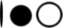
Solid Stream
This type of nozzle provides a high impact per unit area and is used in many cleaning applications, for example, tank-cleaning nozzles (fixed or rotary).
Hollow Cone
This spray pattern is a circular ring of liquid. The pattern is achieved by the use of an inlet orifice tangential to a cylindrical swirl chamber that is open at one end. The circular orifice exit has a diameter smaller than the swirl chamber. The whirling liquid results in a circular shape; the center of the ring is hollow.Hollow cone nozzles are best for applications requiring good atomization of liquids at low pressures or when quick heat transfer is needed. These nozzles also feature large and unobstructed flow passages, which provide a relatively high resistance to clogging. Hollow cone nozzles provide the smallest drop size distributions. The relative range of drop sizes tends to be narrower than other hydraulic styles.
The hollow cone pattern is also achievable by the spiral design of nozzle. This nozzle impinges the fluid upon a protruding spiral. This spiral shape breaks the fluid apart into several hollow cone patterns. By altering the topology of the spiral the hollow cone patterns can be made to converge to form a single hollow cone.
Full Cone
Full cone nozzles yield complete spray coverage in a round, oval or square shaped area. Usually the liquid is swirled within the nozzle and mixed with non-spinning liquid that has bypassed an internal vane. Liquid then exits through an orifice, forming a conical pattern. Spray angle and liquid distribution within the cone pattern depend on the vane design and location relative to the exit orifice. The exit orifice design and the relative geometric proportions also affect the spray angle and distribution. Full cone nozzles provide a uniform spray distribution of medium to large size drops resulting from their core design, which features large flow passages. Full cone nozzles are the style most extensively used in industry.
Flat Spray
As the name implies, the spray pattern appears as a flat sheet of liquid. The pattern is formed by an elliptical or a round orifice on a deflective surface that is tangent to the exit orifice. The orifice has an external groove with a contoured internal cylindrical radius, or “cat’s eye” shape. In the elliptical orifice design, the pattern sprays out of the orifice in line with the pipe. In the deflector design, the spray pattern is perpendicular to the pipe. There are two categories of flat spray, tapered and even, depending on the uniformity of the spray over the spray pattern. Flat spray patterns with tapering edges are produced by straight-through elliptical spray nozzles. This spray pattern is useful for overlapping patterns between multiple nozzle headers. The result is uniform distribution across the entire sprayed surface. Non-tapered flat spray nozzles are used in cleaning applications that require a uniform spray pattern without any overlap in spray area.

Multiple Plume Spray
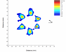
Multiple plume sprays are routinely used in automotive injectors. The multiple plumes are primarily used to provide for the optimal mixing of fuel and air so as to reduce pollutant emission under different operating conditions. The multiple plume automotive injectors can have anywhere from 2 to 8 plumes. The precise location of the centroid of these plumes, the individual plume angles, and the percentage split of the liquid amongst the plumes are normally obtained using an optical patternator.
Capacity
Spray nozzle manufacturers all tabulate capacity based on water. Since the specific gravity of a liquid affects its flow rate, the values must be adjusted using the equation below, where Qw is the water capacity and Spg is the specific gravity of the fluid used resulting the volumetric flow rate of the fluid used Qf.
Nozzle capacity varies with spraying pressure. In general, the relationship between capacity and pressure is as follows:
where Q1 is the known capacity at pressure P1, and Q2 is the capacity to be determined at pressure P2.
Spray Impact
Impact of a spray onto the target surface is expressed as the force/area, N/m2 or lb/in2. This value depends on the spray pattern distribution and the spray angle. Generally, solid stream nozzles or narrow spray angle flat fan nozzles are used for applications in which high impact is desired, such as cleaning. When a nozzle is used for cleaning, the impact or pressure is called impingement. As with all spray patterns, the unit impact decreases as the distance from the nozzle increases, thereby increasing the impact area size.
The spray impact, , depends on the volumetric flowrate Q and pressure drop according to the equation below. The nozzle type and distance between the nozzle and surface affect the constant C.
Spray Angle and Coverage
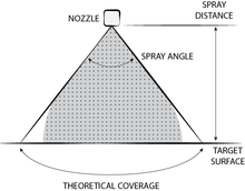
The spray angle diverges or converges with respect to the vertical axis. As illustrated in the figure below, the spray angle tends to collapse or diverge with increasing distance from the orifice. Spray coverage varies with spray angle. The theoretical coverage, C, of spray patterns at various distances may be calculated with the equation below for spray angles less than 180 degrees. The spray angle is assumed to remain constant throughout the entire spray distance. Liquids more viscous than water form smaller spray angles, or solid streams, depending upon nozzle capacity, spray pressure, and viscosity. Liquids with surface tensions lower than water produce wider spray angles than those listed for water. Spray angles are typically measured using optical or mechanical methods. The optical methods include shadowgraphy, extinction tomography, and Mie Imaging.[3] Sprays angles are important in coating applications to prevent overspraying of the coated materials, in combustion engines to prevent wetting of the cylinder walls, and in fire sprinklers to provide adequate coverage of the protected property.

Spray Drop Size
The drop size is the size of the spray drops that make up the nozzle’s spray pattern. The spray drops within a given spray are not all the same size. There are several ways to describe the drop sizes within a spray:
• Sauter Mean Diameter (SMD) or D32
- Fineness of spray expressed in terms of surface area produced by the spray.
- Diameter of a drop with the same volume-to-surface area ratio as the total volume of all the drops to the total surface area of all the drops .
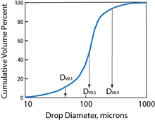
• Volume Median Diameter (VMD) DV0.5 and Mass Median Diameter (MMD)
- Drop size expressed in terms of the volume of liquid sprayed.
- Drop size measured in terms of volume (or mass), with 50% of total volume of liquid sprayed drops with diameters larger than median value and 50% with smaller diameter.
Drop sizes are stated in micrometers (µm). One micrometer equals 1/25,400 inch.
Spray Drop Surface Area Density
The drop surface area density is the product of the spray drop surface area and the number of drops per unit volume. The surface area density is very important in evaporation and combustion applications since the local evaporation rate is highly correlated to the surface area density. The extinction of light caused by the drops within a spray is also directly proportion to the surface area density. The two most widely used methods of measuring the surface area density are Laser Sheet Imaging and Statistical Extinction Tomography.[4]
Drop Size Distribution
The size and/or volume distribution of drops in a spray is typically expressed by the size versus the cumulative volume percent.

Relative Span Factor
Comparing drop size distributions from alternate nozzles can be confusing. The Relative Span Factor (RSF) reduces the distribution to a single number. The parameter indicates the uniformity of the drop size distribution. The closer this number is to one, the more uniform the spray will be (i.e. tightest distribution, smallest variance from the maximum drop size, Dmax, to the minimum drop size, Dmin ). RSF provides a practical means for comparing various drop size distributions.
Drop size measurement
Sprays are typically characterized by statistical quantities obtained from size and velocity measurements over many individual droplets. The most widely used quantities are size and velocity probability density distributions as well as fluxes, e.g., number, mass, momentum etc. Through a given plane, some instruments infer such statistical quantities from individual measurements, e.g., number density from light extinction, but very few instruments are capable of making direct size and velocity measurements of individual droplets in a spray( Kalantari and Tropea, 2007). The three most widely used methods of drop size measurements are laser diffraction, optical imaging, and phase Doppler. All of these optical methods are non-intrusive. If all the drops had the same velocity, the measurements of drop size would be the identical for all methods. However, there is a significant difference between the velocity of larger and smaller drops. These optical methods are classified as either spatial or flux based. A spatial sampling method measures the drops in a finite measurement volume. The residence time of drops in the measurement volume affects the results. The flux-based methods sample continually over a measurement cross-section.
Laser diffraction,[5] a spatial sampling method, relies on the principle of Fraunhofer diffraction, which is caused by the light interacting with the drops in the spray. The scattering angle of the diffraction pattern is inversely related to the size of the drop. This nonintrusive method utilizes a long cylindrical optical probe volume. The scattered light passes through a special transforming lens system and is collected on a number of concentric photodiode rings. The signal from the photodiodes is used to back-calculate a drop size distribution. A number of lenses allow measurements from 1.2 to 1800 µm.
The optical imaging method uses a pulsed light, laser or strobe, to generate the shadow graphic image used to determine the size of the drop in the measurement volume. This spatial measurement method has a range from 5 µm to 10,000 µm with lens and optical configuration changes. Image analysis software processes the raw images to determine a circular equivalent drop diameter. This method is best suited to quantify larger diameter drops in medium to low density sprays, opaque liquids (slurries), and ligaments (partially formed drops).
Phase Doppler,[6] a flux-based method, measures particle size and velocity simultaneously. This method, also known as PDPA, is unique because the drop size and velocity information is in the phase angle between the detector signals and the signal frequency shift. Because this method is not sensitive to intensity, it is used in more dense sprays. The range of drop sizes is 1 to 8000 µm. At the heart of the method are crossed laser beams that create interference patterns (regular spaced pattern of light and dark lines) and illuminate drops as they pass through the small measurement zone. A series of three off axis detectors collects the optical signal that is used to determine the phase angle and frequency shift caused by the drops.
Optical imaging and phase Doppler methods measure the size of individual drops. A sufficient number of drops (order of magnitude 10,000 drops) must be quantified to produce a representative distribution and to minimize the effect of random fluctuations. Often several measurement locations in a spray are necessary because the drop size varies over the spray cross-section.
Factors Affecting Drop Size
Nozzle type and capacity: Full cone nozzles have the largest drop size, followed by flat spray nozzles. Hollow cone nozzles produce the smallest drop size. Spraying pressure: Drop size increases with lower spraying pressure and decreases with higher pressure. Flow rate: Flow rate has a direct effect on drop size. An increase in flow rate will increase the pressure drop and decrease the drop size, while a decrease in flow rate will decrease the pressure drop and increase the drop size.
Spray angle: Spray angle has an inverse effect on drop size. An increase in spray angle will reduce the drop size, whereas a reduction in spray angle will increase the drop size.
Liquid properties: Viscosity and surface tension increase the amount of energy required to atomize the spray. An increase in any of these properties will typically increase the drop size.
Within each type of spray pattern the smallest capacities produce the smallest spray drops, and the largest capacities produce the largest spray drops. Volume Median Diameter (VMD) is based on the volume of liquid sprayed; therefore, it is a widely accepted measure
Practical Considerations
Drop size data depend on many variables, and are always subject to interpretation. The following guidelines are suggested to facilitate understanding and effective use of the drop size data.
Data collection repeatability and accuracy
A drop size test is repeatable if the data from individual tests do not deviate by more than ±10%. If a test result indicates a VMD of 100 µm, another test with results ranging from 90 to 110 µm can be considered identical.
Instrumentation and reporting bias
To make valid data comparisons, particularly from different sources, it is extremely important to know the type of instrument and range used, the sampling technique, and the percent volume for each size class. Instrumentation and reporting bias directly affect drop size data.
Consider the Application
Select the drop size mean and diameter of interest that is best suited for the application. If the object is simply to compare the drop size of alternate nozzles, then the VMD or SMD report are sufficient. Additional information such as RSF, DV90, DV10, and others[7] should be used when appropriate.
References
- ↑ A.H. Lefebvre, Atomization and Sprays, 1989, ISBN 0-89116-603-3
- ↑ Lipp, Charles W. , Practical Spray Technology: Fundamentals and Practice , 2012, ISBN 978-0-578-10090-6
- ↑ Sivathanu et al., Atomization and Sprays, vol. 20, pp. 85-92.
- ↑ Lim, J., and Sivathanu, Y., “Optical Patternation of a Multi-hole Fuel Spray Nozzle,” Atomization and Sprays, vol. 15, pp. 687-698, 2005
- ↑ E. Dan Hirleman, W.D. Bachalo, Philip G. Fenton, editors, Liquid Particle Size Measurement Techniques 2nd Volume, ASTM STP 1083, 1990
- ↑ H.-E. Albrecht, M. Borys, N. Damaschke, C. Tropea, Laser Doppler and Phase Doppler Measurement Techniques, 2003, ISBN 3-540-67838-7
- ↑ Rudolf J. Schick, An Engineer’s Practical Guide to Drop Size Spraying Systems Co. [2009]
- ↑ Kalantari, D.; Tropea, C. "Phase Doppler measurements of spray/wall interaction". Exp. in Fluids. 33: 525–544.